HVAC Zoning Problems: Does Zoning Hurt Airflow and Equipment Lifespan?

Sometimes I hear contractors and technicians saying things like, “HVAC zoning is bad for airflow, it’ll shorten the life of the blower unit, it’ll damage the air conditioning compressor, it’ll cause this bad thing or that bad thing…” In a properly designed system, HVAC zoning won’t do any of things. In this blog, we’ll focus on a bigger problem that actually damages the equipment. Hint: It’s not an HVAC zoning problem at all!
What Static Pressure Readings Mean
In our blog on measuring ductwork capacity, we took a look at static pressure, primarily focusing on the supply duct and evaluating for zone breakdown. There is something else that’s as important, if not more important. What is it? Return duct sizing with filter selection. When HVAC zoning is installed, we start to measure static pressures. Technicians will see a high TESP, or total external static pressure. They will instantly think that the HVAC zoning system is the cause. Is the zoning system the problem, though? If we measure these four static pressure points, we often find that there’s a large imbalance between the supply and the return side of the equipment. The return ESP might significantly exceed design. This is the elephant in the room that often goes ignored. Let’s look into why this imbalance is happening.
Pay Attention to Filter Data
Filter manufacturers provide filter data sheets that include performance charts showing pressure drops. For instance, the Aprilaire Data Sheet gives their filter models, CFM, and pressure drop across the filter at that specific CFM (see page 11). Sometimes, when selecting a filter, technicians only pay attention to maximum airflow, to the exclusion of the rest of that data.
Let’s look at the MERV 13 Upgrade Kits, since these have a lot of crossover with the most common filters used, from Honeywell to Filtrete. The data says the maximum airflow capacity for both the 1213 (20×25) and 1413 (16×25) is 2000 CFM. The pressure drops, however, are recorded for 1200 CFM. On the 1213, the pressure drop at 1200 CFM is 0.15, while the pressure drop on the 1413 is 0.17.
This is what the technician needs to be aware of. If the filter data shows the pressure drop with 1200 CFM (3-tons) is greater than 20% of the furnace TESP then the filter isn’t really designed for 2000 CFM because you’re trying to pull 40% more air through a filter that’s already more restrictive than proper design.
There are a lot of filters to choose from, and some of the data is easy to find, and some of the data isn’t. Filtrete isn’t killing the furnace much to the popular opinion of many HVAC technicians. It is also not an HVAC zoning problem. What’s really causing the issue is poor field design. This poor design also robs from the HVAC zoning budget.
Return Duct Sizing
When it comes to designing a return air duct, ACCA Manual D recommends 600 FPM for the main ducting and 400 FPM for the branch ducts. Take note that these are a little different than supply ducting, which would be 700 FPM for the main trunk and 450 FPM for branches. These two formulas are what I teach contractors when I cover duct design with zoning in mind:
SQ.IN. = (CFM*144) / FPM
CFM = (SQ.IN.*FPM) / 144
Return kits sold by distributors often have a 24×10 drop and return filter boot, so let’s work with these numbers to start.
24×10 = 240 SQ.IN.
CFM = (240*600) / 144 = 1000
This means a 24×10 duct can only handle 1000 CFM of air, so according to proper design a 24×10 return can only handle 2.5 tons of airflow. Yet often this size drop is used for blowers up to 4 tons of air.
If we work that formula differently, wanting to find out what size duct is necessary, then we can start with our known CFM 3 Ton blower that requires 1200 CFM. Again, Manual D recommends 600 FPM for the main ducting.
SQ.IN. = (1200*144) / 600 = 288
Common drop depth is 24 inches, so 288 / 24 = 12. I would then know that for 1200 CFM of air, I require a return drop of 24×12. This is that elephant. Answering tech calls here at Arzel Zoning, we take some regarding airflow. When we collect the static pressure numbers and start reviewing duct sizes, the data often points to the return air as the major source of trouble, not the zoning system.
Air Filter Sizing
If you’ve made it this far, you might be asking, “What about the filter?” The simplest way I can explain best practice, after reviewing different OEM filter data sheets, is velocity to cross-section. The depth of the pleats aren’t really important; they simply allow for more dirt before replacing the filter. What matters is the cross-section and the MERV rating. (Cross section is simply Height*Width, or 20×25 = 500 SQ.IN.)
MERV 13 – 200 FPM
MERV 11 – 250 FPM
MERV 8 – 300 FPM
As many people are more conscious about air contaminants, planning for the MERV 13 is a wise choice. Space constraints might limit the size that you can use, though. A system should have at least a MERV 8 to protect the evaporator coil from dirt and dust that would pass through cheaper filters.
There’s some wiggle room between the design pressure drop of 0.10” and the equipment maximums that are sometimes as high as 0.25”. (This maximum is with a dirty filter, not a clean one.) To allow for actual capture of allergens, it’s best to always be as close to 0.10” as possible, so that a dirty filter doesn’t exceed maximums for OEM blower data. Putting this into practice, 3-ton systems are one of the most common sizes we run across.
(1200*144) / 200 = 864 SQ.IN.
Common filter depth is 25”. Divide 864 by 25 for a cross-section of 24×35. That means if our customers want to use MERV 13 filters, we would need 2x filters. For the sake of sticking with common filter sizes a 3-ton system would need 2x 16×25” (25×32 total). The pressure drop would be slightly higher than 0.10” but we’d be in range of nominal design and maximum. Most importantly, it would relieve one of the most common restrictions within the HVAC system that hinders system operation, and is the greater cause for problems contractors and technicians usually associate with zoning.
Your Design Work is Crucial in HVAC Zoning and Beyond
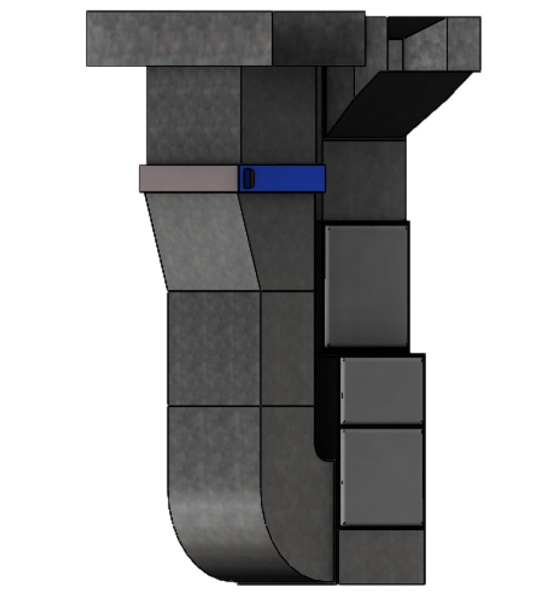
Designing for proper pressure drop across the filter can seem like a daunting task of space. However, when it comes to installing filters, a good solution is to install them in the return drop rather than on the side of the furnace. (See diagram below.)

I hope you find this helpful. Remember that the things that are hindering operation aren’t always the component we’re unfamiliar with. Don’t assume it’s an HVAC zoning problem. It could be something in the design.
If you have questions about airflow and HVAC zoning systems, we at Arzel Zoning would be happy to help. Don’t hesitate to call 800-611-8312.
~JR, Tech Support at Arzel Zoning


